
A logic gate is an electronic circuit which
(1) Makes logic decisions
(2) Allows electrons flow only in one direction
(3) Works binary algebra
(4) Alternates between 0 and 1 values

Subtopic: Logic gates |
Level 3: 35%-60%
Hints

A gate has the following truth table
P 1 1 0 0
Q 1 0 1 0
R 1 0 0 0
The gate is
(1) NOR
(2) OR
(3) NAND
(4) AND
Subtopic: Logic gates |
82%
Level 1: 80%+
Hints
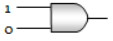
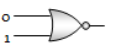
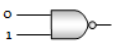
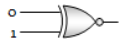
Subtopic: Logic gates |
85%
Level 1: 80%+
Hints


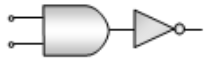

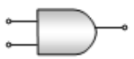
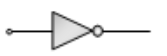
What will be the input of A and B for the Boolean expression
(1) 0, 0
(2) 0, 1
(3) 1, 0
(4) 1, 1
Subtopic: Logic gates |
75%
Level 2: 60%+
Hints
If A and B are two inputs in AND gate, then AND gate has an output of 1 when the values of A and B are
(1) A = 0, B = 0
(2) A = 1, B = 1
(3) A = 1, B = 0
(4) A = 0, B = 1
Subtopic: Logic gates |
93%
Level 1: 80%+
Hints


Subtopic: Logic gates |
89%
Level 1: 80%+
Hints

Subtopic: Logic gates |
85%
Level 1: 80%+
Hints

Subtopic: Logic gates |
92%
Level 1: 80%+
Hints


To get an output 1 from the circuit shown in the figure, the input must be

(1) A = 0, B = 1, C = 0
(2) A = 1, B = 0, C = 0
(3) A = 1, B = 0, C = 1
(4) A = 1, B = 1, C = 0
Subtopic: Logic gates |
92%
Level 1: 80%+
Hints

© 2026 GoodEd Technologies Pvt. Ltd.