
 Q. No.
A n-p-n transistor operates in a common emitter mode as shown. The value of \(R_{L}\) is:
\(\small\left ( \text{Given,}I_{C}=4 mA,~V_{CE}=4~V,V_{BE}=0.6~V~\text{and}~\beta _{dc}=100 \right )\\\)

1. 1 k
2. 2 k
3. 3 k
4. 4 k
\(\small\left ( \text{Given,}I_{C}=4 mA,~V_{CE}=4~V,V_{BE}=0.6~V~\text{and}~\beta _{dc}=100 \right )\\\)


| 1. | It requires a low operational voltage. |
| 2. | It has a fast on-off switching capability. |
| 3. | The bandwidth of the emitted light is \(100\) A to \(10000\) A. |
| 4. | It does not require warm-up time. |
The variation of output potential with input potential in a transistor in CE-mode can be best represented as:
| 1. |  |
2. |  |
| 3. |  |
4. |  |


A combination of logic gates is shown in the circuit. If \(A\) is at \(0\) V and \(B\) is at \(5\) V, then the potential of \(R\) is:

| 1. | \(0\) V | 2. | \(5\) V |
| 3. | \(10\) V | 4. | Any of these |
How many minimum number of NOR gates are required to obtain an AND gate?
1. One
2. Two
3. Three
4. Five
The circuit shown below is an electrical analogue for which of the following logic gates?
1. AND gate
2. OR gate
3. NOT gate
4. NOR gate

What is the equivalent resistance across the terminals of the battery if the diodes are ideal?
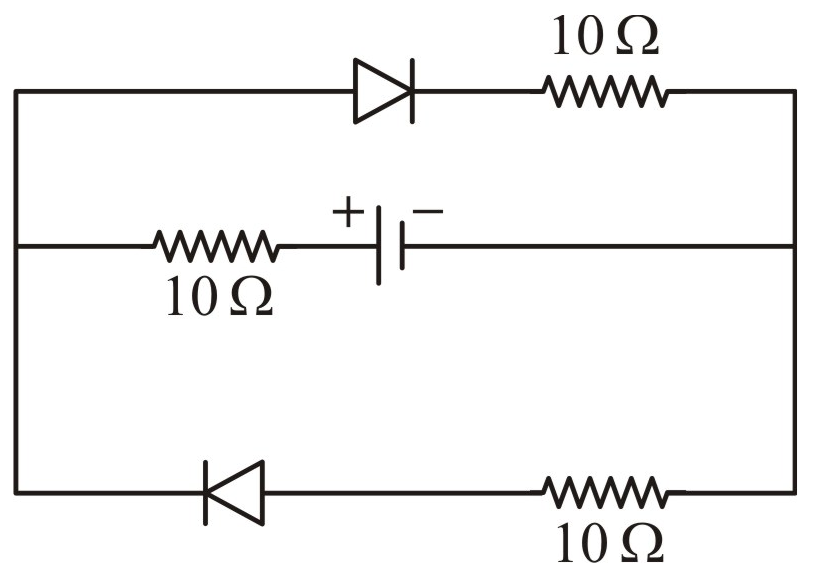
| 1. | \(10~ \Omega\) | 2. | \(20~ \Omega\) |
| 3. | \(15~ \Omega\) | 4. | \({10\over3} ~ \Omega\) |
In an amplifier, an npn-transistor is used in common-emitter mode. If =25, then what will be the collector current if emitter current is 13 mA?
1. 13.5 mA
2. 12.5 mA
3. 11 mA
4. 10.5 mA
What is the name of the logic gate represented by the following symbol?

1. NOR
2. OR
3. NAND
4. AND

© 2024 GoodEd Technologies Pvt. Ltd.