The temperature coefficient of resistance of a wire is 2. If its temperature is increased by 200, then the percentage increase in its resistance will be:
1. 2%
2. 0.2%
3. 4%
4. 0.4%
When the battery of emf V is applied across a conductor AB, the drift speed of electrons through the conductor is v. If the battery is replaced by a battery of emf , then the new drift speed of free electrons will be: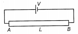
1. v
2.
3. 2v
4. Zero
A current passes through a wire of variable cross-section in steady-state as shown. Then incorrect statement is:

| 1. | Current density increases in the direction of the current. |
| 2. | Potential increases in the direction of the current. |
| 3. | Electric field increases in the direction of the current. |
| 4. | Drift speed increases in the direction of the current. |
The current in a wire varies with time according to the equation \(I=(4+2t),\) where \(I\) is in ampere and \(t\) is in seconds. The quantity of charge which has passed through a cross-section of the wire during the time \(t=2\) s to \(t=6\) s will be:
| 1. | \(60\) C | 2. | \(24\) C |
| 3. | \(48\) C | 4. | \(30\) C |
The length of a conductor is doubled keeping the volume constant. Percentage increase in its resistance is:
(1) 100%
(2) 200%
(3) 300%
(4) 400%
Which of the following graph represents the variation of resistivity () with temperature (\(T\)) for copper?
| 1. |  |
2. |  |
| 3. |  |
4. |  |
The colour code of resistance is given below:
The values of resistance and tolerance, respectively are:
1. 47 k, 10%
2. 4.7 k, 5%
3. 470 , 5%
4. 470 k, 5%
A carbon resistor of (47 ± 4.7) kΩ is to be marked with rings of different colours for its identification. The colour code sequence will be:
1. Violet - Yellow - Orange - Silver
2. Yellow - Violet - Orange - Silver
3. Yellow - Green - Violet - Gold
4. Green - Orange - Violet - Gold
The smallest resistance that can be obtained by the combination of n resistors each of resistance R is:
1. n2R
2. nR
3.
4.
The resultant resistance value of n resistors, each of r ohms and connected in series is x. When those n resistors are connected in parallel, the resultant value is
1.
2.
3.
4.
In the circuit shown in the figure, the effective resistance between A and B is:
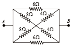
1. 2
2. 4
3. 6
4. 8
Find the equivalent resistance between A and E (the value of each resistor is R).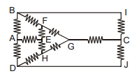
(1)
(2)
(3)
(4)
The figure below shows currents in a part of the electric circuit. The current \(i\) is:

| 1. | \( 1.7 ~\text{A} \) | 2. | \( 3.7~\text{A} \) |
| 3. | \( 1.3~\text{A} \) | 4. | \( 1~\text{A} \) |
The current I in the circuit shown below is: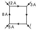
1.
2. 3 A
3. 13 A
4. 20 A
What is the ratio of currents flowing in the resistors \(x\) and \(y\) of resistance \(10~\Omega\) each?

1. \(1\)
2. \(0.5\)
3. \(1.5\)
4. \(2.0\)
The total current supplied to the circuit by the battery in the given circuit is: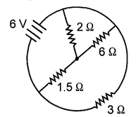
1. 1 A
2. 2 A
3. 4 A
4. 6 A
The reading of an ideal voltmeter in the circuit shown is:
1. 0.6 V
2. 0 V
3. 0.5 V
4. 0.4 V
For the circuit given below, Kirchhoff's loop rule for the loop \(BCDEB\) is given by the equation:
| 1. | \(-{i}_2 {R}_2+{E}_2-{E}_3+{i}_3{R}_1=0\) |
| 2. | \({i}_2{R}_2+{E}_2-{E}_3-{i}_3 {R}_1=0\) |
| 3. | \({i}_2 {R}_2+{E}_2+{E}_3+{i}_3 {R}_1=0\) |
| 4. | \(-{i}_2 {R}_2+{E}_2+{E}_3+{i}_3{R}_1=0\) |
As the switch S is closed in the circuit shown in the figure, the current passed through it is:
(1) 4.5 A
(2) 6.0 A
(3) 3.0 A
(4) Zero
Twelve wires of equal resistance \(R\) are connected to form a cube. The effective resistance between two diagonal ends \(A\) and \(E\) will be:
| 1. | \(\dfrac{5 R}{6}\) | 2. | \(\dfrac{6 R}{5}\) |
| 3. | \(12 R\) | 4. | \(3 R\) |


