The voltage reading on the voltmeter \(V\) in the circuit shown below will be:

| 1. | zero | 2. | \(100\) V |
| 3. | \(200\) V | 4. | \(300\) V |
If the current in an AC circuit is given as when an emf is applied across the circuit. The circuit has components-
1. L and C
2. L and R
3. C and R
4. None of these
A step-down transformer is employed to reduce the main supply of AC from \(220~\text{V}\) to \(11~\text{V}\). If the primary coil draws a current of \(5~\text{A}\) and the secondary supplies a current of \(90~\text{A}\), then the efficiency of the transformer is:
1. \(10\%\)
2. \(95\%\)
3. \(90\%\)
4. \(80\%\)
At resonance, the value of the power factor of the circuit is -
1. 1
2. Zero
3. Between zero and 1
4. More than 1
In a LCR circuit having L = 8.0 henry, C = 0.5 and R = 100 in series, the resonance frequency (in Hz) is
1.
2.
3.
4.
In a LCR series network, . The supply voltage is
1. 25V
2. 75V
3. 35V
4. Zero
The ratio of the number of turns in secondary to primary in an ideal transformer varies from 50 to 550. If the power input is P, then its output power is -
1. 11P
2.
3.
4. P
Loss in energy in the transformer is due to
1. Hysteresis
2. Eddy current loss
3. Leakage of flux
4. All of these
An
1. \(\dfrac{i_1+i_2}{\sqrt{2}}\)
2. \(\dfrac{(i_1+i_2)^2}{\sqrt{2}}\)
3. \(\sqrt{\dfrac{i_1^2+i^2_2}{2}}\)
4. \(\dfrac{\sqrt{i_1^2+i^2_2}}{2}\)
In a step-up transformer, the turn ratio is 1:2. A Leclanche cell (e.m.f. 1.5V) is connected across the primary coil. The voltage developed in the secondary coil would be-
1. 3.0 V
2. 0.75 V
3. 1.5 V
4. Zero
A \(220~\text{V}, 50~\text{Hz}\) AC source is connected to an inductance of \(0.2~\text{H}\) and a resistance of \(20~\Omega\) in series. What is the current in the circuit:
1. \(10~\text{A}\)
2. \(5~\text{A}\)
3. \(33.3~\text{A}\)
4. \(3.33~\text{A}\)
A step-down transformer is connected to 2400 volts line and 80 amperes of current is found to flow in output load. The ratio of the turns in primary and secondary coil is 20 : 1. If transformer efficiency is 100%, then the current flowing in primary coil will be
1. 1600 A
2. 20 A
3. 4 A
4. 1.5 A
The potential difference V and the current i flowing through an instrument in an ac circuit of frequency f are given by volts and I = 2 sin ωt amperes (where ω = 2πf). The power dissipated in the instrument is
1. Zero
2. 10 W
3. 5 W
4. 2.5 W
A generator produces a voltage that is given by V = 240 sin 120 t, where t is in seconds. The frequency and r.m.s. voltage are
1. 60 Hz and 240 V
2. 19 Hz and 120 V
3. 19 Hz and 170 V
4. 754 Hz and 70 V
If a current I given by flows in an ac circuit across which an ac potential of has been applied, then the power consumption P in the circuit will be
1.
2.
3.
4. P = 0
An alternating current is given by the equation . The r.m.s. current is given by
1.
2.
3.
4.
In an ac circuit, the current is given by and the ac potential is V = 200 sin(100t) volt. Then the power consumption is :
1. 20 watts
2. 40 watts
3. 1000 watts
4. 0 watt
In a LCR circuit having L = 8.0 henry, C = 0.5 μF and R = 100 ohm in series. The resonance frequency in radian per second is
1. 600 radian/second
2. 600 Hz
3. 500 radian/second
4. 500 Hz
The impedance of a circuit consists of 3 ohm resistance and 4 ohm reactance. The power factor of the circuit is :
1. 0.4
2. 0.6
3. 0.8
4. 1.0
The power factor of a good choke coil is:
1. Nearly zero
2. Exactly zero
3. Nearly one
4. Exactly one
The phase difference between the current and voltage of LCR circuit in series combination at resonance is
1. 0
2. π/2
3. π
4. –π
In a series LCR circuit, resistance R = 10Ω and the impedance Z = 20Ω. The phase difference between the current and the voltage is
1. 30°
2. 45°
3. 60°
4. 90°
The power factor of an ac circuit having resistance (R) and inductance (L) connected in series and an angular velocity ω is
1.
2.
3.
4.
In an LR-circuit, the inductive reactance is equal to the resistance R of the circuit. An e.m.f. applied to the circuit. The power consumed in the circuit is:
1.
2.
3.
4.
In the circuit shown in figure neglecting source resistance the voltmeter and ammeter reading will respectively, will be
1. 0V, 3A
2. 150V, 3A
3. 150V, 6A
4. 0V, 8A
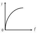
An ac source of variable frequency f is connected to an LCR series circuit. Which one of the graphs in the figure represents the variation of the current I in the circuit with frequency f :
1.
2.
3.
4.

1. \(a\)
2. \(b\)
3. \(c\)
4. \(d\)
| 1. | \(\frac{1}{100}~\text{sec}\) | 2. | \(\frac{1}{200}~\text{sec}\) |
| 3. | \(\frac{1}{300}~\text{sec}\) | 4. | \(\frac{1}{400}~\text{sec}\) |
An alternating current is given by the equation The r.m.s. current is given by
1.
2.
3.
4.
In the adjoining figure, the impedance of the circuit will be 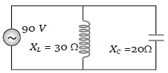
1. 120 ohm
2. 50 ohm
3. 60 ohm
4. 90 ohm
An inductor 20 mH, a capacitor 50μF, and a resistor 40Ω are connected in series across a source of emf V=10sin340t. The power loss in the AC circuit is:
1. 0.67 W
2. 0.78W
3. 0.89 W
4. 0.46 W
The rms value of potential difference V shown in the figure is

(1)
(2)
(3)
(4)
A coil has resistance and inductive reactance at 50 Hz frequency. If an AC source of 200 V, 100 Hz, is connected across the coil, the current in the coil will be:
1.
2.
3.
4.
Power dissipated in an L-C-R series circuit connected to an AC source of emf is
(a)
(b)
(c)
(d)
The natural frequency of the circuit shown in the figure is
(1)
(2)
(3)
(4) None of these
A step –down transformer transforms a supply line voltage of 2200 volt into 220 volt. The primary coil has 5000 turns. The efficiency and power transmitted by the transformer are 90% and 8 kilowatt respectively. Then the number of turns in the secondary is:
1. 5000
2. 50
3. 500
4. 5
The root-mean-square value of an alternating current of \(50~\text{Hz}\) frequency is \(10 ~\text A\). The time taken by the alternating current to reach from zero to maximum value and peak value will be:
1. \(2×10^{–2}~\text s\) and \(14.14 ~\text A \)
2. \(2×10^{–2}~\text s\) and \(7.07~\text A\)
3. \(5×10^{–3}~\text s\) and \(7.07~\text A\)
4. \(5×10^{–3}~\text s\) and \(14.14 ~\text A \)
Match List I (expression for current) with list II (RMS value of current) and select the correct answer.
List I List II
A. I = (i)
B. (ii)
C. (iii)
D. (iv)
A B C D
(1) 4 2 1 3
(2) 4 2 3 1
(3) 2 4 3 1
(4) 2 4 1 3
Turn ratio in a step-up transformer is 1: 2 if a
Lechlanche cell of 1.5 V is connected across the
input, then the voltage across the output will be:
1. 0.1 V
2. 1.5 V
3. 0.75 V
4. zero
In an ideal parallel LC circuit, the capacitor is
charged by connecting it to a D.C. source which
is then disconnected. The current in the circuit:
1. becomes zero instantaneously
2. grows monotonically
3. decays monotonically
4. oscillates instantaneously
A power transmission line feeds input power at 2300V to a step down transformer with its primary windings having 4000 turns, giving the output power at 230 V. If the current in the primary of the transformer is 5A, and its efficiency is 90%, the output current would be:
1. 50 A
2. 45 A
3. 25 A
4. 20 A
At a moment (t = 0), when the charge on capacitor C1 is zero, the switch is closed. If I0 be the current through inductor at t = 0 , for t > 0
1. maximum current through inductor equals I0/2.
2. maximum current through inductor equals
3. maximum charge on
4. maximum charge on
A wire of resistance R is connected in series with an inductor of reactance L. Then quality factor of RL circuit is
1.
2.
3.
4.
The primary and secondary coils of a transformer have 5O and 1500 turns respectively. If the magnetic flux linked with the primary coils is given by = + 4t, where is in webers, t is time in second and is a constant, the output voltage across the secondary coil is
1. 120 V
2. 220 V
3. 30 V
4. 90 V
Which of the following combinations should be selected for better tuning of an LCR circuit used for communication?
1. R = 25 , L = 2.5 h, C = 45
2. R = 15 , L = 3.5 h, C = 30
3. R = 25 , L = 1.5 h, C = 45
4. R = 20 , L = 1.5 h, C = 35