The equivalent capacitance between A and B is as the given figure:

1. \(16 \pi \epsilon_ 0 r\)
2. \(4 \pi \epsilon_ 0 r\)
3. \(8 \pi \epsilon_ 0 r\)
4. None of these
In the circuit shown in the figure, the energy stored in \(6~\mu\text{F}\) capacitor will be:

| 1. | \(48 \times10^{-6}~\text{J}\) | 2. | \(32 \times10^{-6}~\text{J}\) |
| 3. | \(96 \times10^{-6}~\text{J}\) | 4. | \(24 \times10^{-6}~\text{J}\) |
Two identical metal plates are given charges respectively. If they are now brought close to form a parallel plate capacitor with capacitance , the potential difference between them is :
1.
2.
3.
4.
The capacity of parallel plate condenser depends on
1. The type of metal used
2. The thickness of plates
3. The potential applied across the plates
4. The separation between the plates
If the dielectric constant and dielectric strength be denoted by \(k\) and \(x\) respectively, then a material suitable for use as a dielectric in a capacitor must have:
1. high \(k\) and high \(x\).
2. high \(k\) and low \(x\).
3. low \(k\) and low \(x\).
4. low \(k\) and high \(x\).
A spherical condenser has inner and outer spheres of radii a and b respectively. The space between the two is filled with air. The difference between the capacities of two condensers formed when outer sphere is earthed and when inner sphere is earthed respectively will be
1. Zero
2.
3.
4.
Two insulated metallic spheres of 3 μF and 5 μF capacitances are charged to 300 V and 500V respectively. The energy loss, when they are connected by a wire is
1. 0.012 J
2. 0.0218 J
3. 0.0375 J
4. 3.75 J
Four plates of equal area A are separated by equal distances d and are arranged as shown in the figure. The equivalent capacity is
1.
2.
3.
4.
Three capacitors are connected to D.C. source of 100 volts shown in the adjoining figure. If the charge accumulated on plates of C1, C2 and C3 are and qf respectively, then
1.
2.
3.
4.
A capacitor of capacity C1 is charged to the potential of V0. On disconnecting with the battery, it is connected with a capacitor of capacity C2 as shown in the adjoining figure. The ratio of energies before and after the connection of switch S will be
1. (C1 + C2)/C1
2. C1/(C1 + C2)
3. C1C2
4. C1/C2
In the adjoining figure, four capacitors are shown with their respective capacities and the P.D. applied. The charge and the P.D. across the 4 μF capacitor will be
1. 600 μC; 150 volts
2. 300 μC; 75 volts
3. 800 μC; 200 volts
4. 580 μC; 145 volts
A capacitor is charged by a battery. The battery is removed and another identical uncharged capacitor is connected in parallel. The total electrostatic energy of the resulting system
1. increases by a factor of 4
2.decreases by a factor of 2
3. remain the same
4. increases by a factor of 2

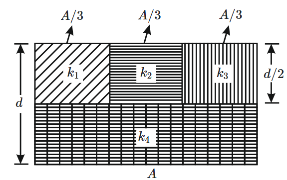
1. \(k = k_{1} + k_{2} + k_{3} + 3 k_{4}\)
3. \(\dfrac{1}{k} = \dfrac{3}{2 \left(k_{1} + k_{2} + k_{3}\right)} + \dfrac{1}{2 k_{4}}\)
4. \(\dfrac{1}{k} = \dfrac{1}{k_{1}} + \dfrac{1}{k_{2}} + \dfrac{1}{k_{3}} + \dfrac{3}{2 k_{4}}\)
A capacitor of \(2~\mu\text{F}\) is charged as shown in the figure. When the switch \(S\) is turned to position \(2\), the percentage of its stored energy dissipated is:

| 1. | \(20\%\) | 2. | \(75\%\) |
| 3. | \(80\%\) | 4. | \(0\%\) |
A parallel plate air capacitor has capacity C, distance of separation between plates is d and potential difference V is applied between the plates. Force of attraction between the plates of the parallel plate air capacitor is
1. C2V2/2d
2. CV2/2d
3. CV2/d
4. C2V2/2d2
Two thin dielectric slabs of dielectric constants K1&K2 () are inserted between plates of a parallel capacitor, as shown in the figure. The variation of electric field E between the plates with distance d as measured from plate P is correctly shown by
1.
2.
3.
4.
Two metallic spheres of radii \(1\) cm and \(3\) cm are given charges of \(-1\times 10^{-2}~\text{C}\) and \(5\times 10^{-2}~\text{C},\) respectively. If these are connected by a conducting wire, the final charge on the bigger sphere is:
1. \(2\times 10^{-2}~\text{C}\)
2. \(3\times 10^{-2}~\text{C}\)
3. \(4\times 10^{-2}~\text{C}\)
4. \(1\times 10^{-2}~\text{C}\)
A 10 μF capacitor and a 20 μF capacitor are connected in series across a 200 V supply line. The charged capacitors are then disconnected from the line and reconnected with their positive plates together and negative plates together and no external voltage is applied. What is the potential difference across each capacitor
1.
2.
3. 400 V
4. 200 V
To form a composite 16 μF, 1000 V capacitor from a supply of identical capacitors marked 8 μF, 250 V, we require a minimum number of capacitors
1. 40
2. 32
3. 8
4. 2